Router? I Hardly Know 'Er - Part 1
This is the first in a series of posts where I’ll be using some old routers I have lying around to practice some hardware hacking/reversing techniques. Today, I’ll focus on showcasing how to:
- Do basic initial device research
- Identify exposed hardware components and debug ports
- Interacting with debug ports using my trusty Buspirate
Profile of the Victim
WRT54Gv2
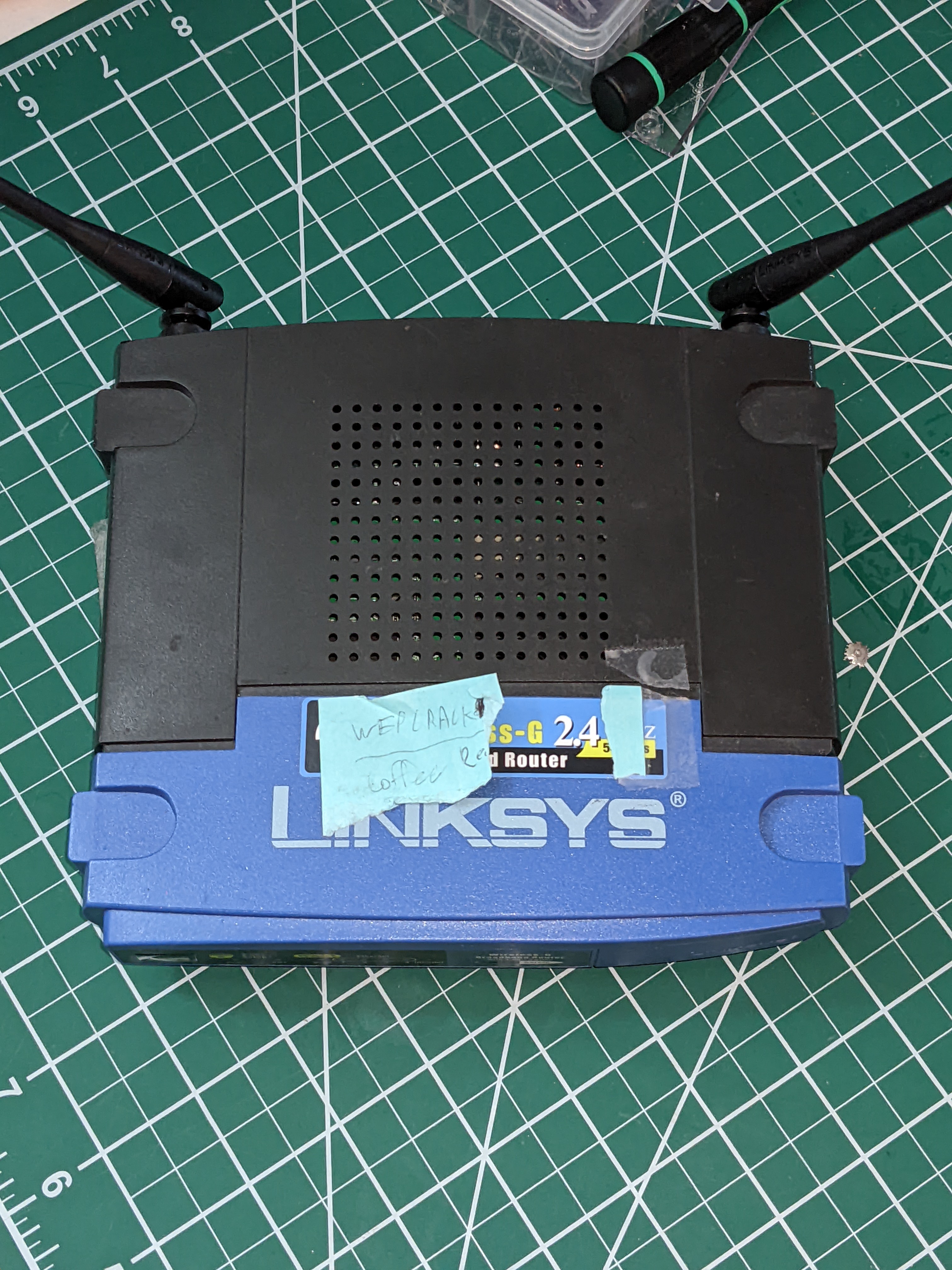
Today, we’ll be taking a look at a Linksys WRT54Gv2 router from the mid 2000s. When I began researching its background, I was surprised to see that this little fella and its similar Linksys cousins developed something of a cult following over the years, to the point of even having their own Wikipedia article. Part of this popularity is thanks to the dedicated folks at the OpenWRT project and the interest of the general router hacking community.
Honestly, I’m incredibly tempted to flash away and start hacking around with OpenWRT, but first thing’s first. Our goal is to at least extract the firmware and any other artifacts from the file system before we start doing anything too destructive.
Casing the Joint
Note that for narrative purpose, I’ve laid out the next few sections in a pretty linear fashion. The reality of my workflow was much more… lets say…. heuristic (see: scattered). I just wanted to clear that up so as to paint a more accurate picture of my actual approach to this initial analysis.
OSINT Gathering
A great place to start with any project like this is to do proper Open Source Intelligence Gathering (OSINT). In other words, we gather any publicly available information we can find about the device. When hunting for documents, we can make use of things like:
- Device’s make, model, serial number
- Schematic/spec sheets for identified Integrated Circuits (ICs) or other board components
- FCC ID
Aside: FCC ID
All devices in the US that communicate on the electromagnetic spectrum (radio, cellular, Wifi, etc.) needs to register and reveal certain information to the FCC. This database, fcc.io is publicly available for anyone to query, and although you may find certain sections are incomplete or redacted, it can be a great starting point for figuring out whats going on with a device.
I’ll spare you some gory details of my full research here, but take a brief moment to mention the wonderful world of Google Dorking/Search Engine hacking and how it may aid you on any OSINT quest. I’ll also leave a few links for some really good places to try to run down info on strange electronics (or general OSINT):
ELECTRONICS & OSINT LINKS
- octopart: part & data sheet sourcer
- alldatasheets: public data sheet library for ICs
- sparkfun: accessible electronic tutorials and information
- awesome-electronics: git repo for electronic enthusiasts. Lots of links here
- OSINT megalist: gitbook of all things OSINT
First Glances
Armed with a bit more knowledge, we can more confidently begin our initial physical analysis of the device. Here, we’ll be keeping an eye out for things like:
- Exposed factory debug ports
- Identifying marks on IC/Chips
- Interesting serial codes/numbers on the board
- Understanding at a high level, the control flow of the board
So lets pop the casing off to get a peek at the guts.
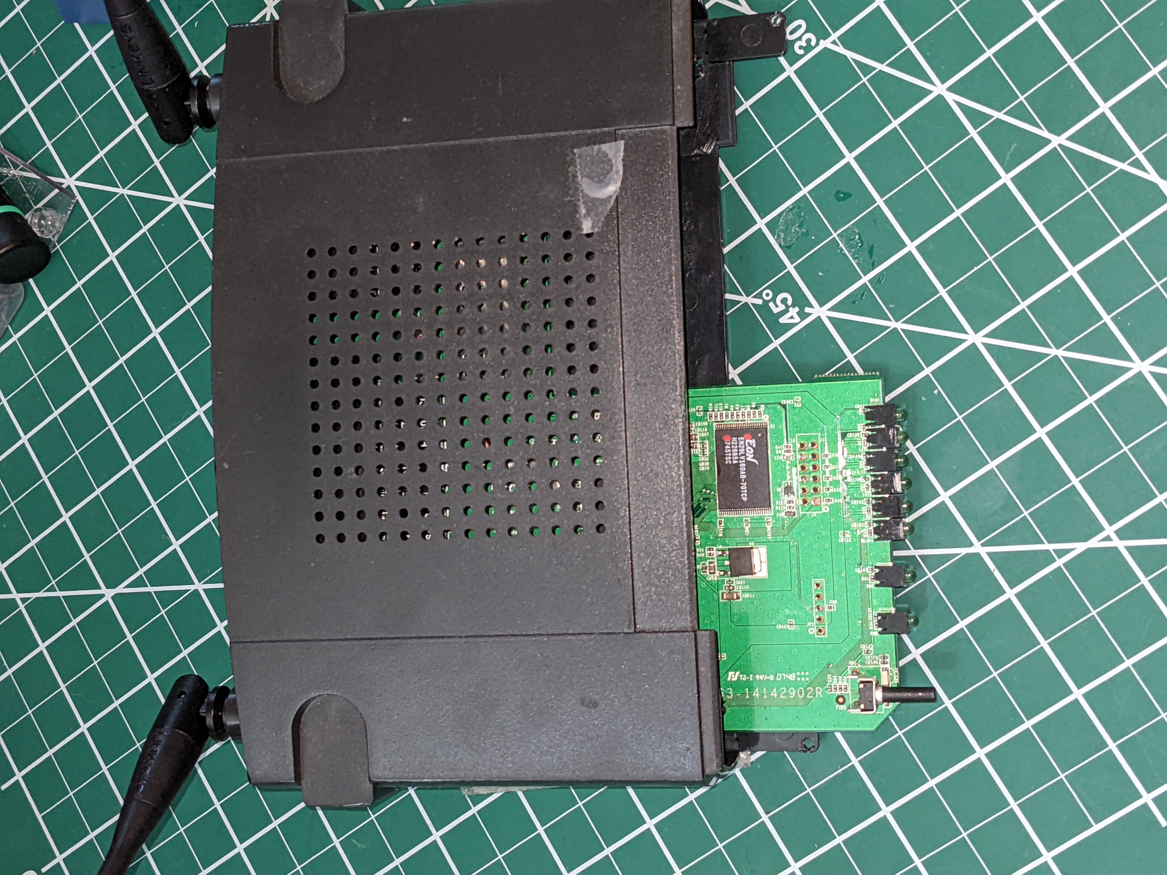
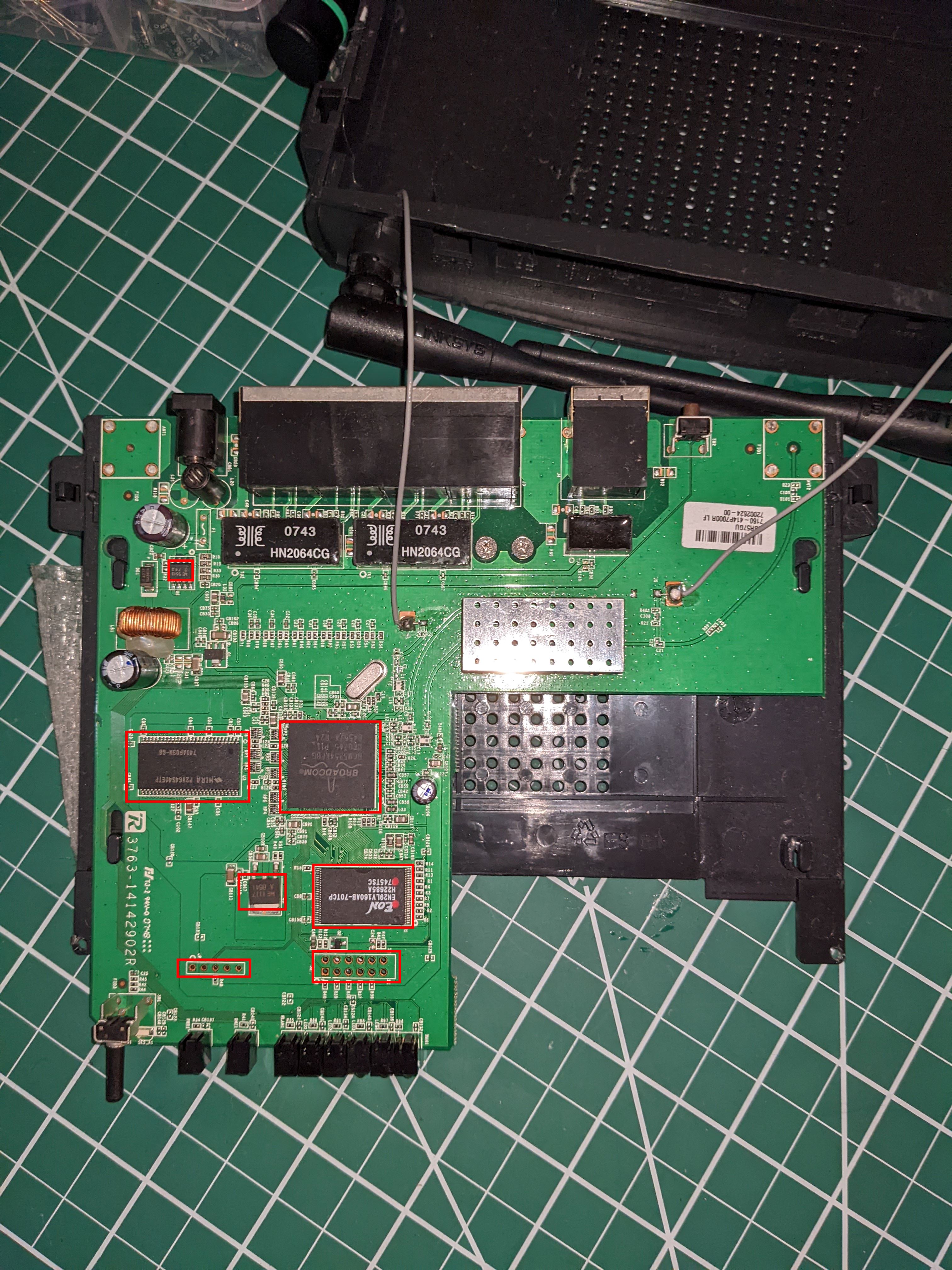
In the above photo I’ve highlighted some areas of interest that will require us to take a closer look. Alright, alright, enough with the photoshoot. Let’s grab a better view of the board components.
Chip ID
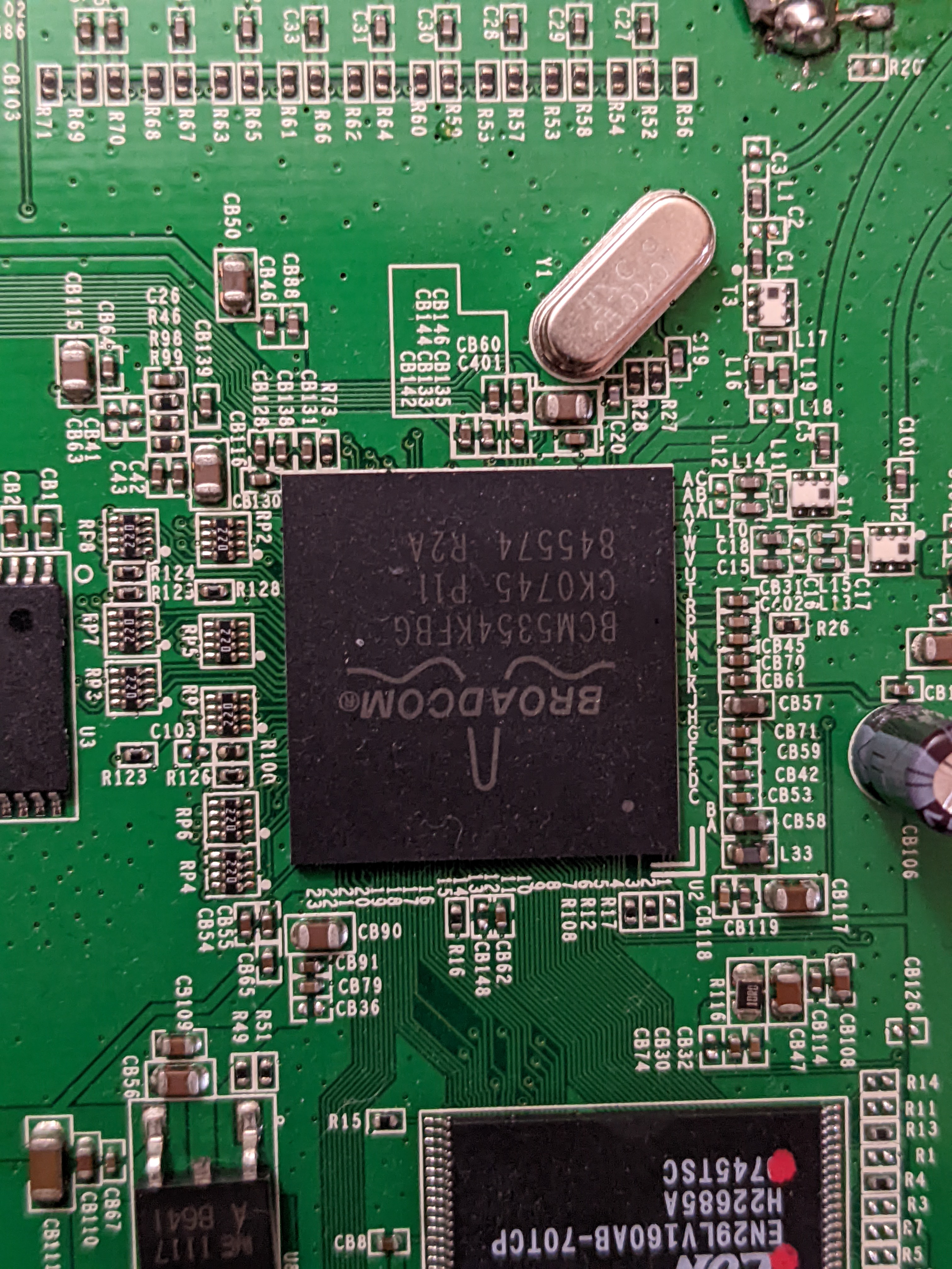
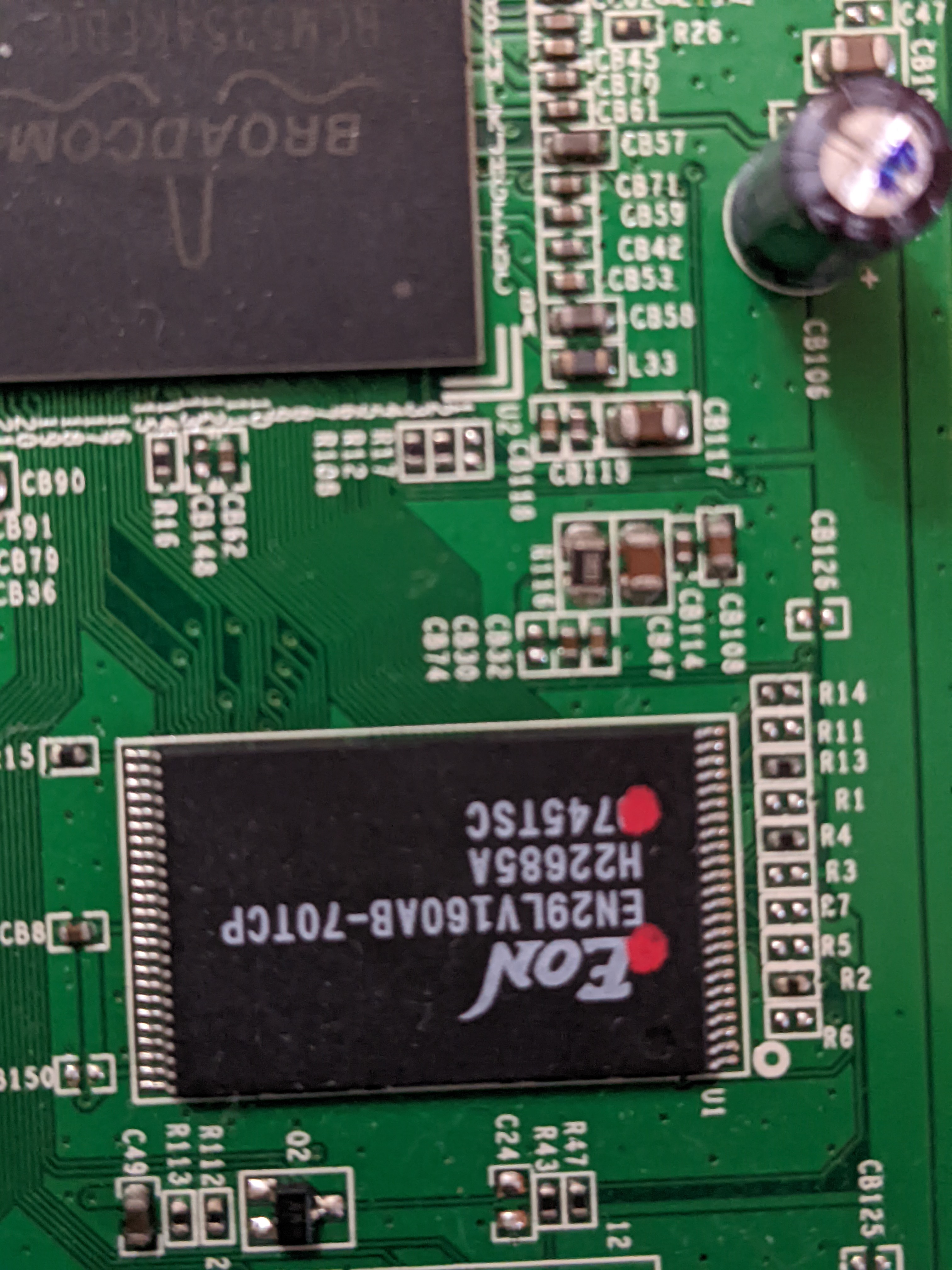
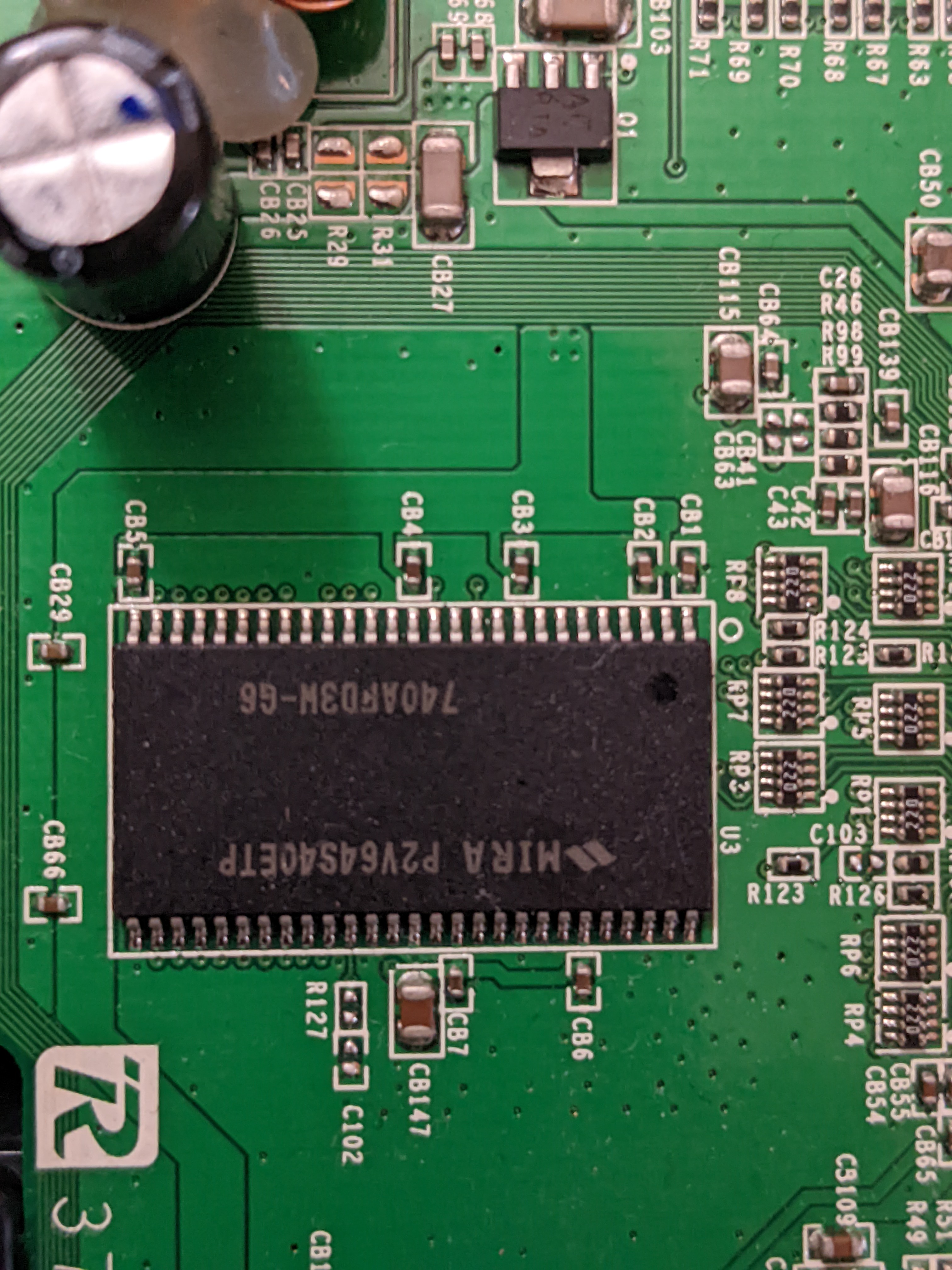
Right off the bat, we can see that there are three main ICs on the board. (I looked up the other two smaller ones and found they were pretty uninteresting)
Broadcom CPU
EON Flash Memory
Mira SDRAM
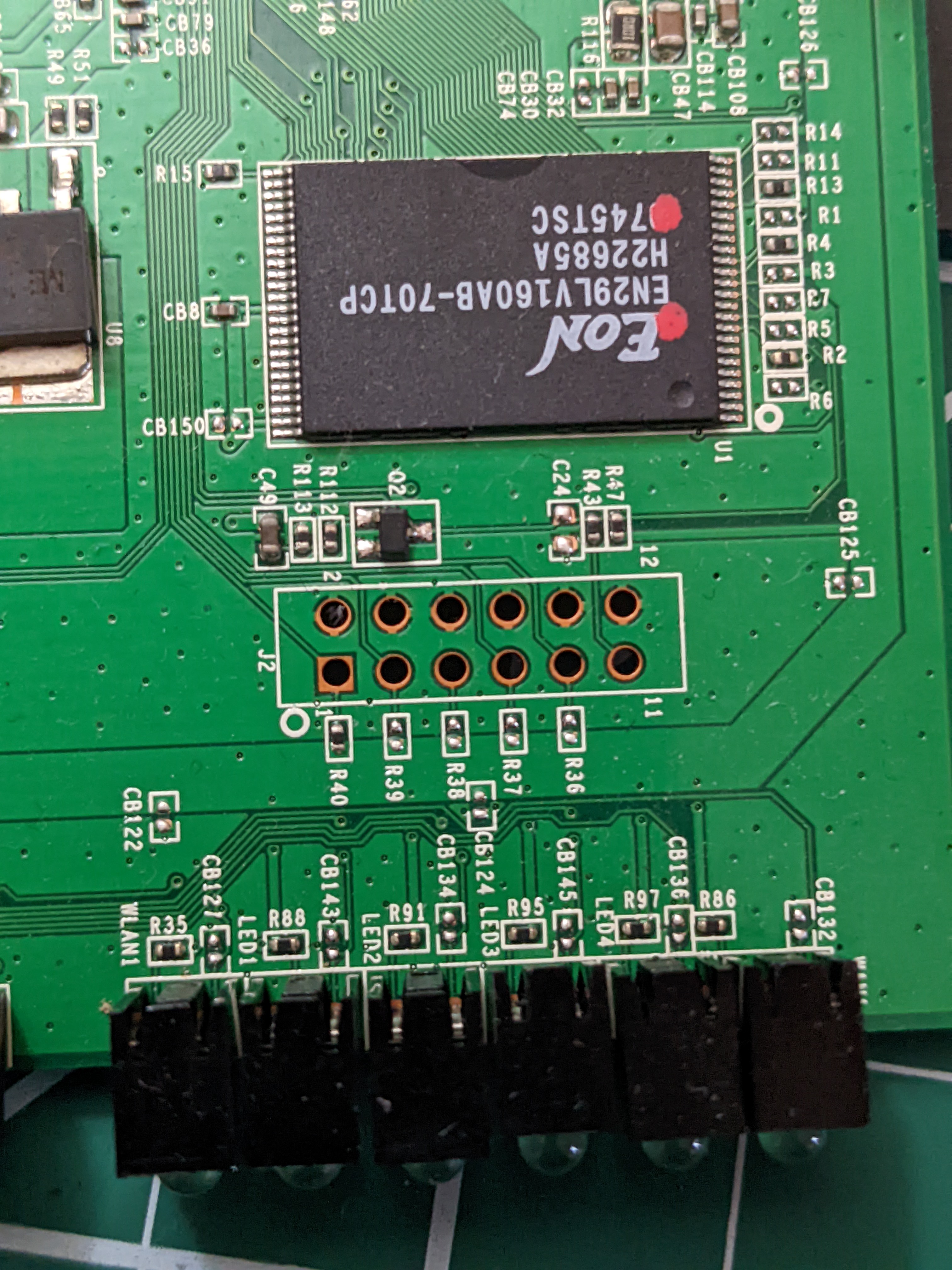
Debug Ports!
Also spotted are traces for what appears to be some very welcome factory debug ports. These ports are used to communicate over serial protocols (UART, JTAG, etc) and are often employed by the device’s manufacturer to do things like QA testing and other build automation-y things at the factory. Point is, they are usually unsecured (cause security == time == money, and who’s got that kind of time amiright?) and can give some fairly privileged access to the device without us having to break a sweat. That is, provided we can accurately ID the serial protocol the device is expecting.
Here’s port one (UART):
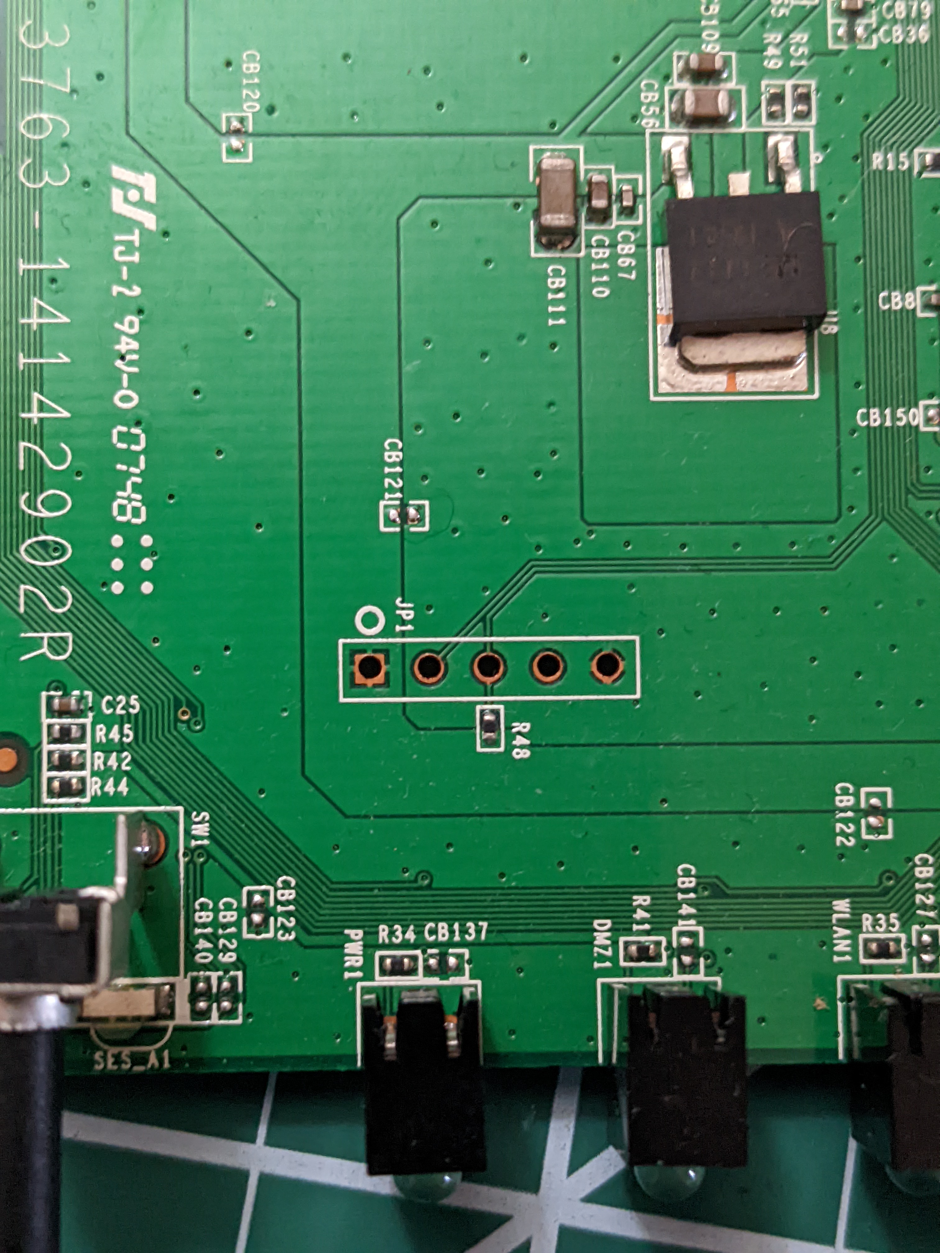
And port two (JTAG):
Recap
To summarize the info we’ve gathered from the device and our OSINT:
| Feature | Data |
|---|---|
| Serial Num. | CDFJ1GCB8996 |
| FCC ID | Q87-WRT54GV82 |
| CPU Type | Broadcom BCM5354KFBG (BCM5354 chip rev 2 SoC) |
| CPU Speed | 240MHz |
| Flash Type | electrically erasable, read/write non-volatile flash memory |
| Flash Chip | EON EN29LV160AB-70TCP |
| Flash Size | 16 MEGABIT (2048K X 8- BIT / 1024 K X 16-BIT) FLASH MEMORY |
| RAM Size | 64 MEGABIT |
| RAM Chip | MIRA P2V64S40ETP (740AFD3W-G6) |
| Switch | Broadcom BCM5354KFBG (BCM5354 chip rev 2 SoC) |
| Port-based vlan | Yes |
| Ethernet Port Count | 1-10/100-WAN 4-10/100-LAN |
| Wired Standard | IEEE 802.3? |
| bootloader | CFE (vxworks boot) |
| Power | 12V/.5A |
| Size | 7.32” x 1.89” x 6.06” |
| USB | No |
| Serial Port | Yes (UART) |
| JTAG Port | Yes |
| Radio (wl0) | |
| Wireless Radio | Broadcom BCM5354KFBG (BCM5354 chip rev 2 SoC) |
| WLAN DSP processor | Broadcom BCM5354KFBG (BCM5354 chip rev 2 SoC) |
| Antenna Connector Type | Fixed |
| Wireless Standard | IEEE 802.11b/g |
| WiFi Operating Frequency | 2.4GHz |
| 802.11g | 6, 9, 12, 18, 24, 36, 48, 54Mbps |
| 802.11b | 1, 2, 5.5, 11Mbps |
| Radio cor_rev | 13 |
| Radio Capabilities | ap sta wet led wme 802.11d 802.11h rm cqa mbss4 afterburner acktiming |
Ahoy, Buspirate!
Before proceeding any further, we should take a second to talk about Buspirate. According to their website, “The Bus Pirate is an open source hacker multi-tool that talks to electronic stuff.” What a massive understatement. Buspirate is a “a universal bus interface”, and it’s basically my swiss army knife for interacting with unknown boards and investigating serial protocols. Personally, I rock a Buspirate v3.6. If hardware hacking tickles your fancy, I highly recommend picking one up for yourself (if you can spring for it, go v4).
I’ll also leave a link here to the command reference guide for convenience and completeness sake.
Quick Start
Windows
With the Windows config, we’re going to have PuTTY play the role of our serial terminal client.
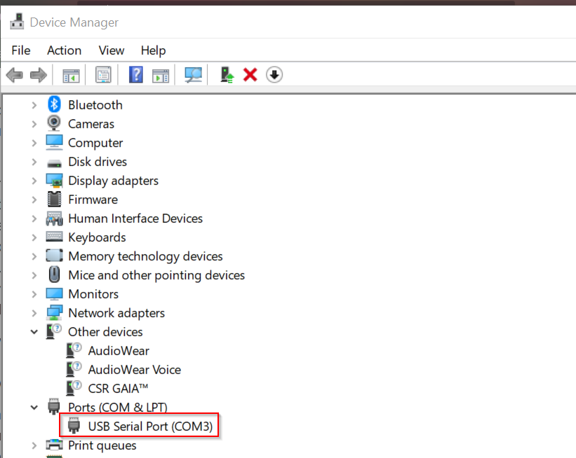
Locate COM Port
Using the native Device Manager program, we can find the COM port number that the OS assigned to Buspirate.
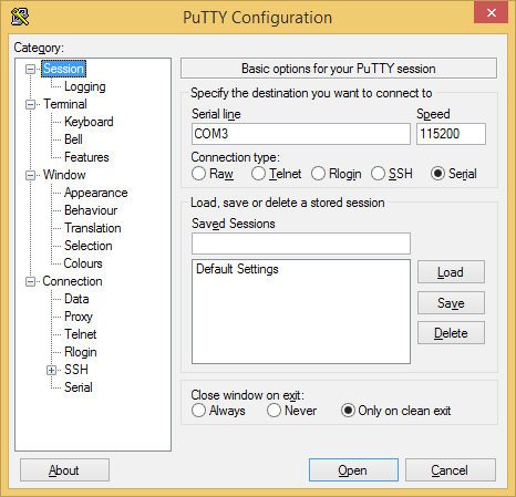
Configure Terminal Connection
Make sure your PuTTY config matches the following photos exactly.
Session tab
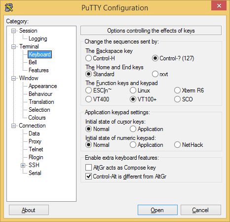
Keyboard tab
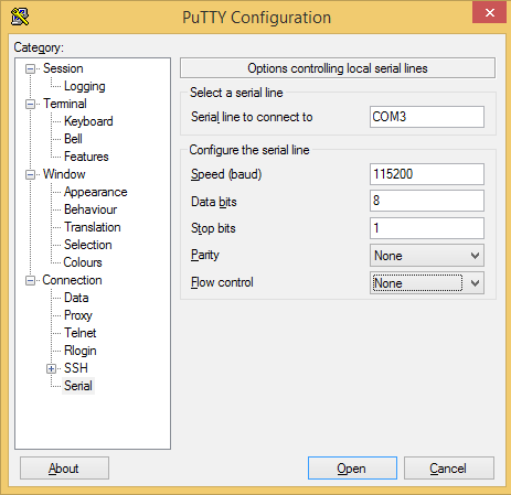
Serial tab
Linux
Here I’ll be configuring Buspirate on the latest version of Kali (so actually Debian). First, we’re gonna need to grab a serial client that we can interface with over our terminal, like minicom.
Prerequisites
- Install minicom
sudo apt-get minicom - Use
lsusbto get the Buspirate device name (here its/dev/bus/usb/001/003)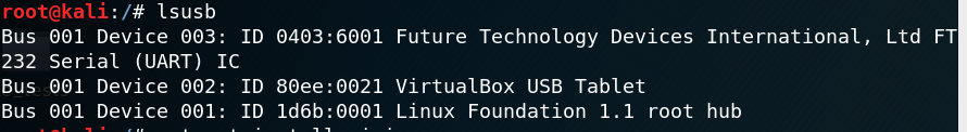
Configure Minicom
- Bring up minicom settings, make sure to configure the right baud rate (115200)! Note that here I’m using
/dev/Buspirateinstead of/dev/bus/usb/001/003. This is because I set up a udev rule to map my Buspirate to the constant name/dev/Buspirateto make it a little easier for me to use.minicom -s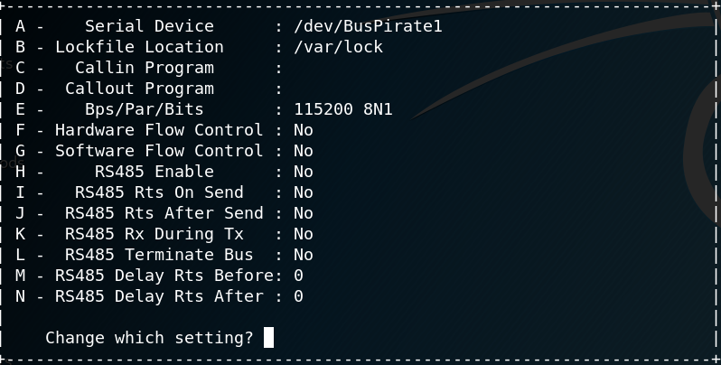
Test Connection
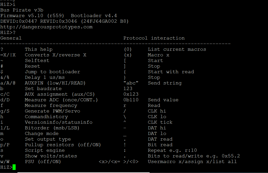
Then launch minicom/PuTTY connection to bring up the Buspirate menu!
Scripting Buspirate
Another handy feature of Buspirate is the ability to interact with the connected device through Buspirate’s scripting capabilities with popular programming languages such as Python and C (and more). Access to scripting makes using Buspirate much more pleasant and fun, considering how easy it is to whip up some Python and make up some input fuzzing patterns to send to the target device.
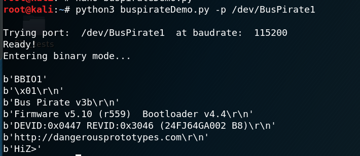
I’ve added some sample code below so you can get an idea of what interacting with Buspirate looks like in Python. You can also find this code on my github. I’ve mostly just adapted what Buspirate’s website offered as a demo, but updated to support Python 3. As you can see, its as simple as importing the serial module and treating Buspirate like any old serial device.
import sys
import serial
import argparse


commands = {
        'BBIO1': b'\x00',    # Enter reset binary mode
        'SPI1':  b'\x01',    # Enter binary SPI mode
        'I2C1':  b'\x02',    # Enter binary I2C mode
        'ART1':  b'\x03',    # Enter binary UART mode
        '1W01':  b'\x04',    # Enter binary 1-Wire mode
        'RAW1':  b'\x05',    # Enter binary raw-wire mode
        'RESET': b'\x0F',    # Reset Bus Pirate
        'STEST': b'\x10',    # Bus Pirate self-tests
}


def arg_auto_int(x):
    return int(x, 0)


class FatalError(RuntimeError):
    def __init__(self, message):
        RuntimeError.__init__(self, message)


def main():
    parser = argparse.ArgumentParser(description = 'Bus Pirate binary interface demo', prog = 'binaryModeDemo')


    parser.add_argument(
            '--port', '-p',
            help = 'Serial port device',
            default = '/dev/ttyUSB0')


    parser.add_argument(
            '--baud', '-b',
            help = 'Serial port baud rate',
            type = arg_auto_int,
            default = 115200)


    args = parser.parse_args()


    print('\nTrying port: ', args.port, ' at baudrate: ', args.baud)


    try:
        port = serial.Serial(args.port, args.baud, timeout=0.1)
    except Exception as e:
        print('I/O error({0}): {1}'.format(e.errno, e.strerror))
        print('Port cannot be opened')
    else:
        print('Ready!')
        print('Entering binary mode...\n')


        count = 0
        done = False
        while count < 20 and not done:
            count += 1
            port.write(commands.get('BBIO1'))
            got = port.read(5)  # Read up to 5 bytes
            print(got)
            if got == b'BBIO1':
                done = True
        if not done:
            port.close()
            raise FatalError('Buspirate failed to enter binary mode')


        # Now that the Buspirate is in binary mode, choose a BP mode
        port.write(commands.get('RESET'))
        while True:
            got = port.readline()
            if not got:
                break
            print(got),
        port.close()

if __name__ == '__main__':
    try:
        main()
    except FatalError as e:
        print('\nA fatal error occurred: %s',e)
        sys.exit(2)
Here’s a quick peek at this script’s output:
Now, back to those debug ports! But first lets go to my research notes so we can have a …
UART Primer
Universal asynchronous receiver-transmitter (UART) is a mechanism for asynchronous serial communication in which the data format and transmission speeds are configurable.
- Asynchronous means the transmission is not synchronized to a common clock signal. Instead, the transmitting and receiving devices send start and stop signals before and after each data frame, respectively.
- Serial means data is sent sequentially (i.e. one bit at a time), over a communication channel or bus. This is as opposed to parallel communication, where several bits are sent as a whole across a link with multiple channels.
In other words, UART is a protocol, communication scheme, and physical hardware that facilitates sequential communication between devices without specifying a common clock signal. Typically, we see UART implemented as a way for an outside serial interface device (used for debugging/testing at the factory) to interact with integrated circuits (IC) on a printed circuit board (PCB). This is commonly done to verify that the components on the PCB were installed correctly, as a form of quality control and manufacturing oversight at the factory.
This means that more often than not, accessing a UART port on a device will give a user unintended access to the devices internals.
Principles of Operation
Central to the idea of UART is the concept of a “shared data bus” between two devices. You can think of this data bus as being a tube for passing messages between the two (or more) components connected to the bus. Since UART operates in serial mode, they must get interpreted by the receiver according to a pre-defined control flow specification. Specifically, UART transmitters send data bits one by one, from the least significant to the most significant, framed by start and stop bits so that precise timing is handled by the communication channel. The receiving party uses another UART to re-assemble the transmitted bits into complete bytes.
Separate interface devices are used to convert the logic level signals of the UART to and from the external signaling levels, which may be standardized voltage levels, current levels, or other signals. Two common signal levels are RS-232, a 12-volt system, and RS-485, a 5-volt system. The UART usually does not directly generate or receive the external signals used between different items of equipment.
UART communication comes in several flavors:
- simplex: in one direction only, with no provision for the receiving device to send information back to the transmitting device
- full duplex: both devices send and receive at the same time
- half duplex: devices take turns transmitting and receiving
Data framing
The idle, no data state is high-voltage, or powered. This standard is remnant of telegraphy, in which the line is held high to show that the line and transmitter are not damaged. Each character is framed as a logic low start bit, data bits, possibly a parity bit and one or more stop bits. In most applications the least significant data bit (the one on the left in this diagram) is transmitted first, but there are exceptions.
The start bit signals the receiver that a new character is coming. The next five to nine bits, depending on the code set employed, represent the character. When employing a parity bit, this gets placed after the data bit section. The next one or two bits are always in the “logic high” condition and called the stop bit(s). They signal to the receiver that the character is complete. Since the start bit is logic low (0) and the stop bit is logic high (1) there are always at least two guaranteed signal changes between characters.
If the line remains in the logic low condition for longer than a character time, then the UART detects this as a “break condition”
Receiver
All operations of the UART hardware are controlled by an internal clock signal which runs at a multiple of the data rate (usually 8 or 16 times the bit rate). The receiver tests the state of the incoming signal on each clock pulse, looking for the beginning of the start bit.
- If the suspected start bit lasts at least one-half of the bit time, it is valid and signals the start of a new character.
- Otherwise, it is considered a “spurious pulse” and is ignored by the receiver.
After waiting a further bit time, the state of the line is again sampled and the resulting level clocked into a shift register. After the required number of bit periods for the character length (5 to 8 bits, typically) have elapsed, the contents of the shift register are made available (in parallel fashion) to the receiving system. The UART will set a flag indicating new data is available, and may send a processor interrupt signal to request that the host processor transfers the received data.
Since communicating UARTs have no shared timing system apart from the communication signal, UARTs resynchronize their internal clocks on each change of the data line that is not considered a spurious pulse. Simplistic UARTs do not do this, instead they resynchronize on the falling edge of the start bit only, and then read the center of each expected data bit, and this system works if the broadcast data rate is accurate enough to allow the stop bits to be sampled reliably.
One feature of UARTs is to store the most recent character while waiting for the next transmission. This “double buffering” gives a receiving computer an entire character transmission time to fetch a received character. Many modern UARTs have a small first-in-first-out (FIFO) buffer memory between the receiver shift register and the host system interface. This buffer provides the processor with ample time to handle an interrupt from the UART and prevents loss of received data at high rates.
Transmitter
Describing transmission in UART is simpler than receiving, since timing does not have to be determined from the line state, nor is it bound to any fixed timing intervals. As soon as the sending system deposits a character in the shift register (after completion of the previous character), the UART:
- Generates a start bit
- Shifts the required number of data bits out to the line
- Generates and sends the parity bit (if used)
- Sends the stop bits.
If in full-duplex mode, since full-duplex operation requires characters to be sent and received at the same time, UARTs use two different shift registers for transmitted and received characters. High performance UARTs could contain a transmit FIFO buffer to allow a CPU or DMA controller to deposit multiple characters in a burst into the FIFO instead of placing one character at a time in the shift register. Note that transmission of a single or multiple characters may take a long time relative to CPU speeds, so a UART maintains a flag showing busy status so that the host system knows if there is at least one character in the transmit buffer or shift register.
Application
Transmitting and receiving UARTs must be set for the bit speed, character length, parity, and stop bits for proper operation. The receiving UART may detect some mismatched settings and set a “framing error” flag bit for the host system. In exceptional error cases, the receiving UART will produce an erratic stream of mutilated characters and transfer them to the host system.
Typically, we use eight data bits, no parity, and one stop bit.
Example in Practice
Recall that UART transmitted data is organized into packets. Each packet contains 1 start bit, 5 to 9 data bits (depending on the UART), an optional parity bit, and 1 or 2 stop bits:
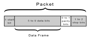
-
The transmitting UART receives data in parallel from the source data bus:
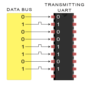
-
The transmitting UART adds the start bit, parity bit, and the stop bit(s) to the data frame:
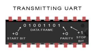
-
The entire packet is sent serially from the transmitting UART to the receiving UART. The receiving UART samples the data line at the pre-configured baud rate:
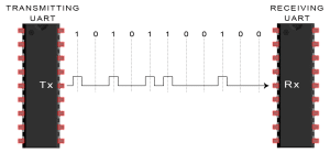
-
The receiving UART discards the start bit, parity bit, and stop bit from the data frame:
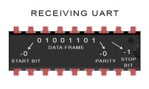
-
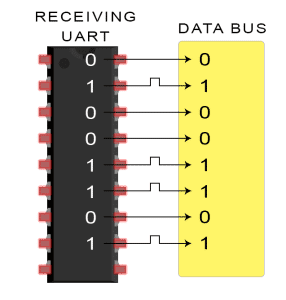
The receiving UART converts the serial data back into parallel and transfers it to the data bus on the receiving end
Quick Setup
UART headers will generally have four pins. See the below table for information on the various pins.
| Pin | Purpose |
|---|---|
| TX | UART Transmission Pin – Data going out of the device will appear on this pin |
| RX | UART Receive Pin - Data destined for the device will go through this pin |
| VCC | Voltage Common. Typical values are 3.3V and 5V |
| GND | Ground |
| CTS | “Clear To Send” - used for hardware flow control (optional) |
| RTS | “Request To Send” - used for hardware flow control (optional) |
When connecting a TTL USB UART adapter, you will get a similar pinout broken out into separate cables. These cables will often have a female header jumper attached to allow for ease of connection.
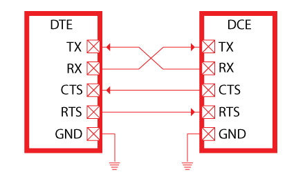
Be sure that your connections are correct! GND (Ground) should be connected to GND. TX (from your UART cable) should be connected to RX on the target device. Likewise, RX (from your UART cable) needs to be connected to the TX header on the target device. (i.e. transmit pins connect to receive pins, and receive pins connect to transmit pins).
Setting Up the Connection
After making the physical connections to the appropriate pins, make sure to configure the serial terminal correctly. This configuration includes selecting an appropriate “baud rate” (bits per second) value. If this value is not set properly, you will not get readable data on your serial terminal. Common baud rates are shown in the table below.
| Baud Rate (bits/sec) |
|---|
| 1200 |
| 2400 |
| 4800 |
| 9600 |
| 19200 |
| 38400 |
| 57600 |
| 115200 |
The baud rate can also be found in datasheets, manufacturer’s instructions, and/or by using certain tools. baudrate.py is an open source python script that will attempt to auto discover the baud rate for the device. Anyone can download the tool from (here)[https://github.com/devttys0/baudrate/blob/master/baudrate.py].
Common Problems
Here are a few common pitfalls one might make when attempting to set up a UART connection
-
Forgetting to cross TX-RX: Always make sure to cross the RX and TX lines between the serial devices. Misconfiguring for TX-TX and RX-RX will cause a troubleshooting headache. Always double check your pin assignments!
-
Inconsistent baud rate: Make sure the baud rates between the two devices are matched up. Since the transmission of data is asynchronous, if the devices are not speaking at the same speed then data can appear garbled or even lose data completely.
The Goods!
Now as promised, here’s a walkthrough of interacting with the device through Buspirate’s UART functionality.
Initial Setup & Troubleshoot
To start, I naively hooked up some jumper wires from the Buspirate to the UART debug port and powered on the device to see what happens.
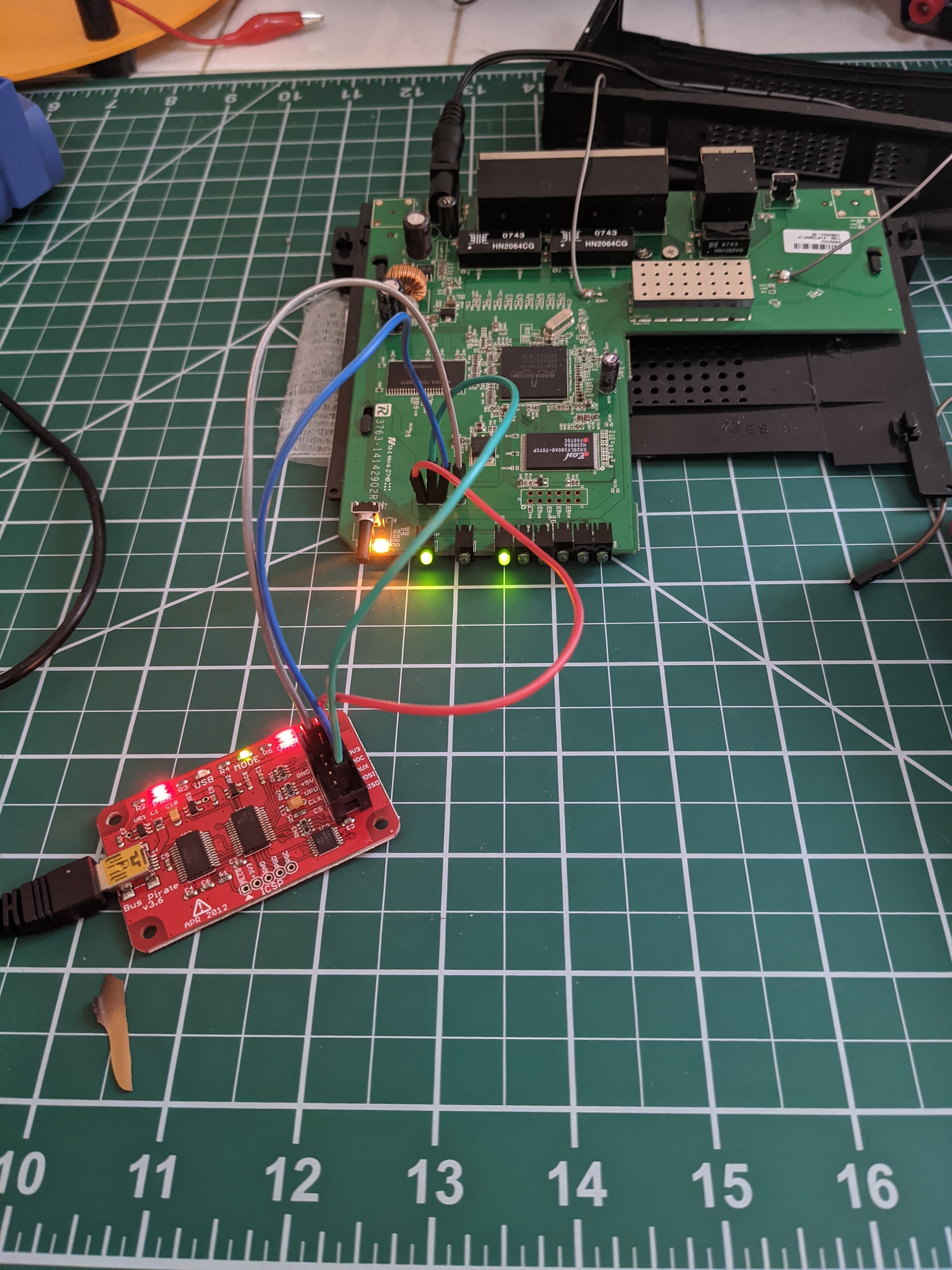
This first part took a bit of trial and error. Admittedly, I had the VCC and GND terminals swapped and was getting no usable output. Note to self: square pinout means VCC and not GND (unless it doesnt, in which case good luck) After a bit of googling, this page helped set me straight.
Here’s a closer look at the successful hookup
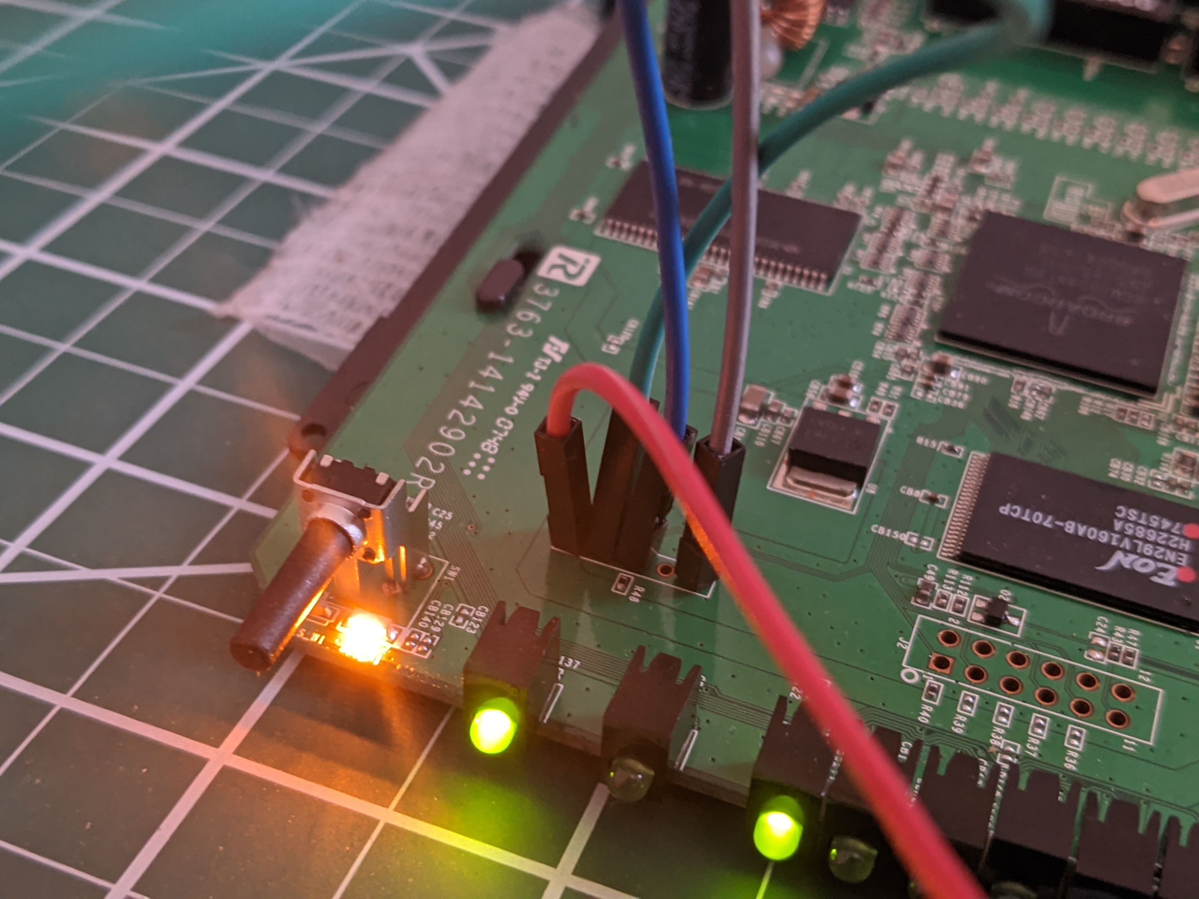
And now, my terminal is alight with what seems to be the device’s boot sequence. Success!
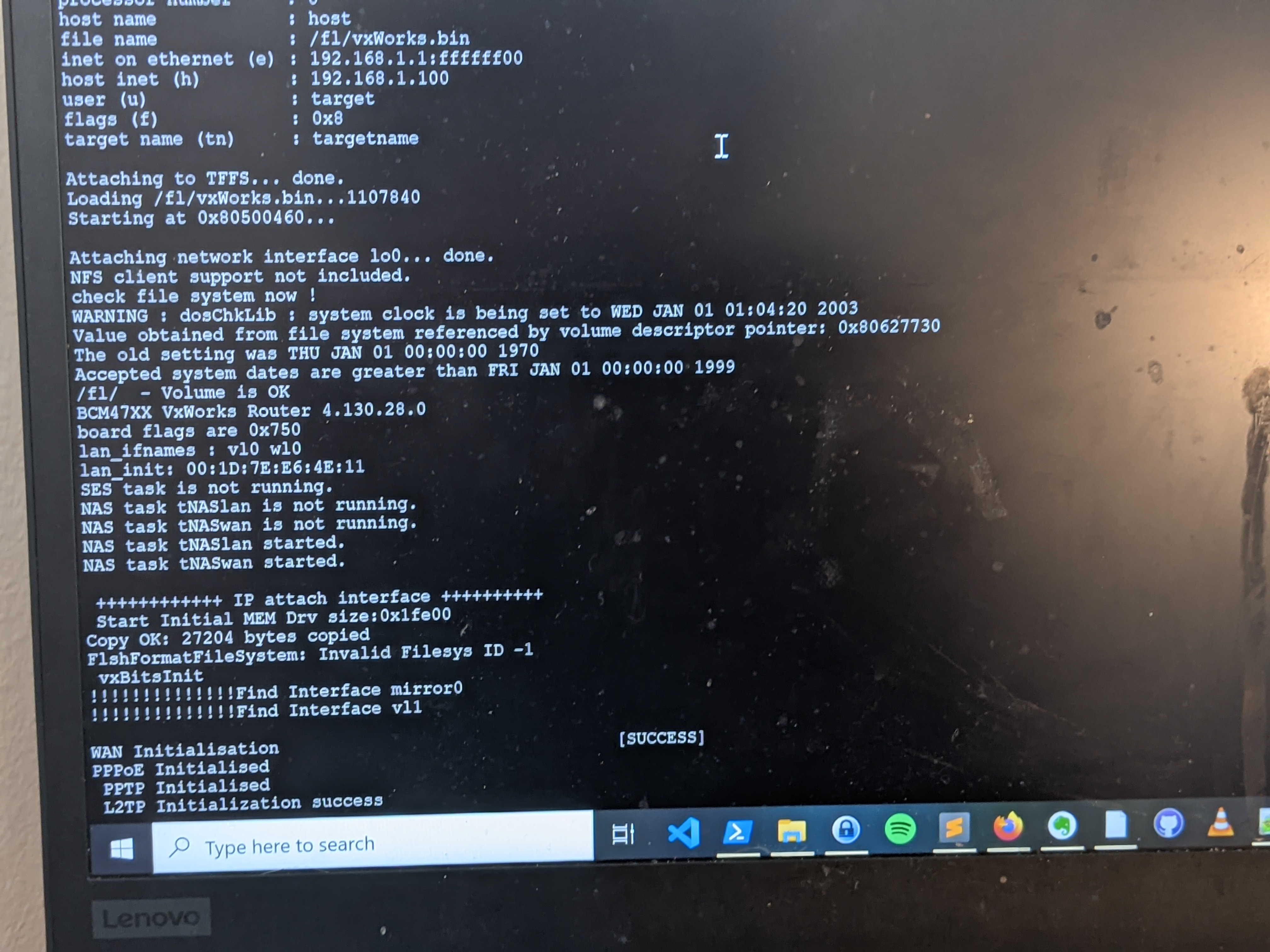
Now that we can see the boot sequence, we can be safe to assume that this UART port provides access to the device’s bootloader. Now, lets see if we can interrupt the automatic boot process and hope we get dropped into a usable shell.
For this part, I would power cycle the device and mash keys on my keyboard to hope that one of them would send the right interrupt signal to the bootloader. In this case, the winning move was to mash the spacebar.
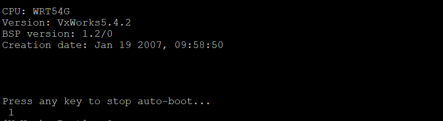
Which then dropped me into this lovely and strange boot shell.

VxWorks is not a brand I’m familiar with, so its going to take even more research to figure out whats going on here. I’ll leave some of the more intimate details for next time, but all that’s important to mention here is that VxWorks is a proprietary Real Time Operating System (RTOS) that has seen use in all kinds of settings, including aerospace devices! What it’s doing in my router, well, is anyone’s guess I suppose.
Bootloader Commands
Typing ? at the command line brings up a list of commands supported by the bootloader.
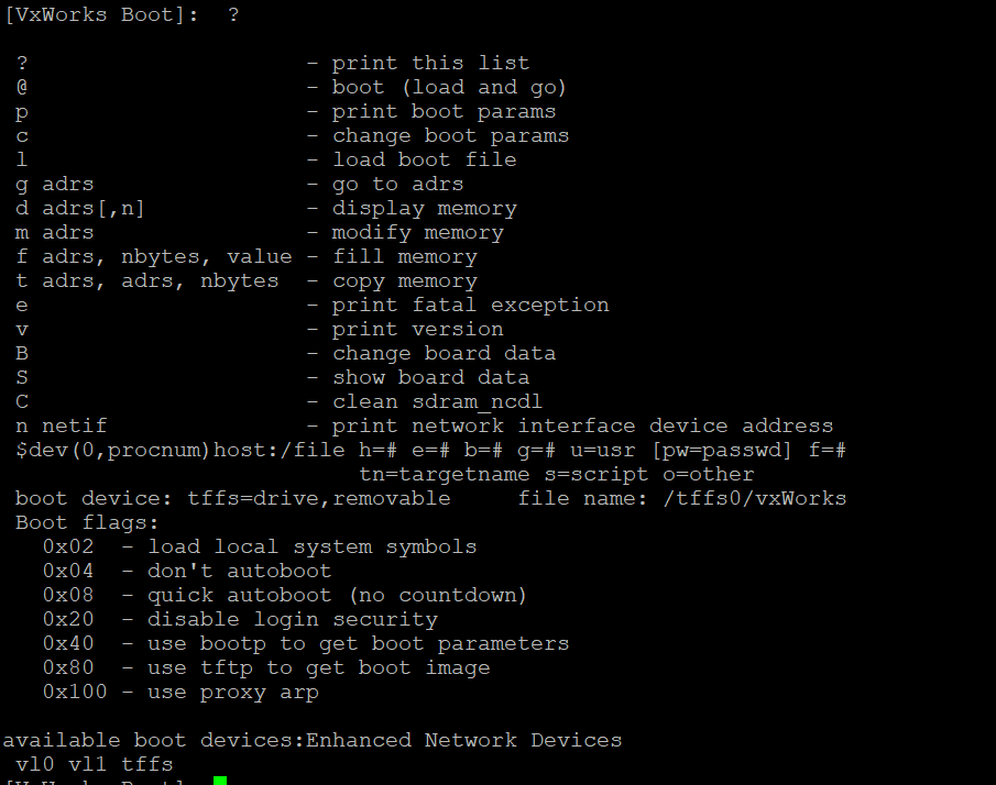
It seems like there’s a lot of things we can do from the bootloader, including arbitrary read/write to memory! For now, let’s try something simple: modify the boot parameters for the device, so it will stop autobooting on initial power and instead drop us directly into the boot shell.
Patching the Boot Image
Consider the following list of boot parameters supported by the bootloader.
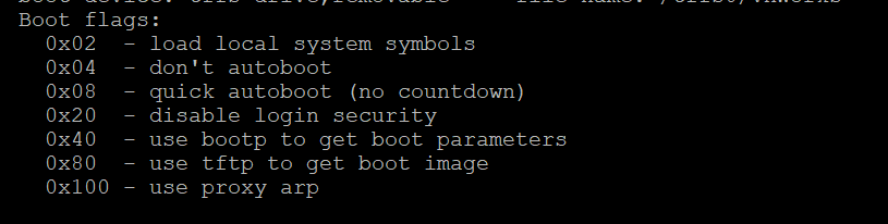
It stands to reason that if we change the boot parameter flags to 0x04, we should be able to stop the autoboot process. We can confirm the existing set of boot parameters by running p
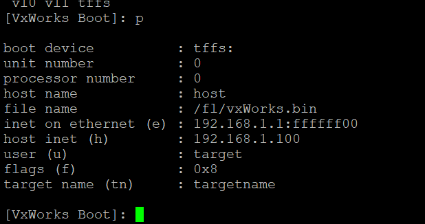
Bingo. The existing boot parameters specify a “fast autoboot option” with boot flag 0x08. Lets use the c command to modify the boot parameters so the flag reads 0x24. As we mentioned, 0x04 will stop the boot process while 0x20 means “disable login security” which may come in handy later. Logically or them together and we get 0x24 as our new boot flag.
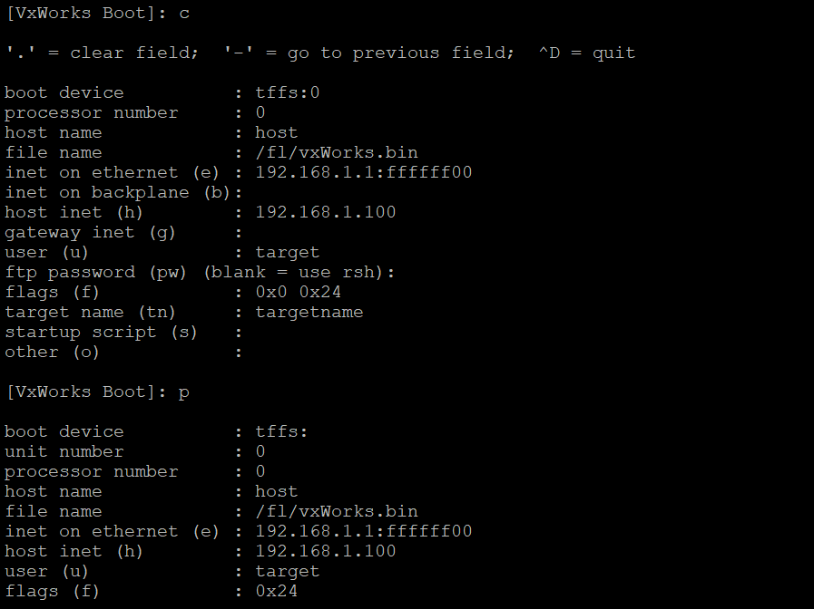
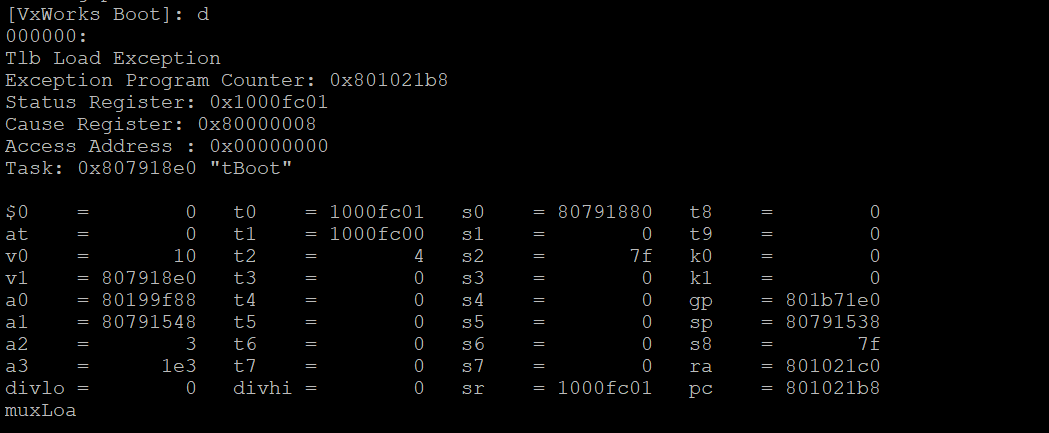
As seen above, we both changed the boot parameters and confirmed that we made the correct changes. At this point we should be able to fully explore the bootloader’s functionality without accidentally triggering a boot. For example, now we can display memory with the d command without being forced into autoboot!
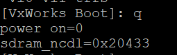
“Undocumented Features”
Something quick and cheeky I can showcase here is an “undocumented feature” I found from fuzzing some inputs to the bootloader’s menu. Typing q at the bootloader command select brings up the following info on the device’s sdram.
Next Steps
I’ll saving a deeper dive on VxWorks, bootloader shenanigans, and JTAG for the next installment, since this post is already pretty lengthy.
Join me again soon-ish while I walk through the next steps: extracting firmware from the device!
Source(s):
- https://fccid.io/
- https://the-dark-web.com/google-dorks/
- http://dangerousprototypes.com/docs/Bus_Pirate
- http://buspirate.com/tutorial/bus-pirate-command-guide?format=pdf
- https://www.insidegadgets.com/2010/11/20/inside-the-belkin-f1up0002-wireless-g-all-in-one-print-server/
- https://en.wikipedia.org/wiki/Asynchronous_serial_communication
- https://en.wikipedia.org/wiki/Universal_asynchronous_receiver-transmitter
- https://www.circuitbasics.com/basics-uart-communication/
- https://learn.sparkfun.com/tutorials/serial-communication/rules-of-serial
- https://learn.sparkfun.com/tutorials/serial-communication/wiring-and-hardware
- https://learn.sparkfun.com/tutorials/serial-communication/uarts
- https://learn.sparkfun.com/tutorials/serial-communication/common-pitfalls
- https://github.com/devttys0/baudrate/blob/master/baudrate.py
- https://d.lij.uno/linux-bus-pirate.html
- https://www.ee.ryerson.ca/~courses/ee8205/Data-Sheets/Tornado-VxWorks/vxworks/ref/bootLib.html